(Subscribe to this discussion)
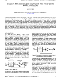
Continuous-time feedback loops are very popular in the design of class-D power amplifiers where an analog signal is converted to a high power pulse-stream feeding the load. Such loops embed a continuous-time loop filter network, a comparator and a switching power stage. The loop is either synchronized by injection of a carrier signal (e.g. triangle or sawtooth waveform) or is free-running (self-oscillating). Traditionally, the dynamics of these loops are analyzed by using linearized continuous-time models where the comparator is modeled as a gain. However, this method fails to accurately explain several important characteristics such as noise aliasing, image components and loop stability. This paper analyses the sampling nature of the comparator and derives a general linear discrete-time loop small-signal model which can be applied to loops of any order. An important conclusion is that the comparator gain only depends on the slope at zero crossings and not of the amplitude of the comparator input signal. In addition, the model shows important differences between synchronized and free running loops which is demonstrated on simple 1st–order cases.
Click to purchase paper as a non-member or you can login as an AES member to see more options.
|
Rajdeep Mukhopadhyay |
Comment posted May 22, 2022 @ 01:47:09 UTC
(Comment permalink)
Hi All, I have recently become a member of AES and the reason was this paper and some other by Lars Risbo. I am trying to develop a fast simulation set up to estimate/simulate class-D output noise. Right now, what I am finding is that AC analysis with average PWM model is optimistic, PSS/PNOISE is closer to silicon but still not quite there, and most frustatingly time to time suffers from convergence and/or accuracy issues. Add to that long simulation time of the latter. The main purpose of the PSS/PNOISE was to estimate the inband mixing due to high frequency components which is getting sampled by the PWM comparator. This paper seems to provide a method to model the entire feedback loop which does not use the average PWM model. But I stuggle to use the model outlined in this paper for my purposes. I have found a relevant paper from the same author which is easier to understand e.g. "A Versatile Discrete-Time Approach for Modeling Swich-Mode Controllers". That paper provides an equation for Ks(f) at 50% dutyc cycle and proposes a model (Figure 5). But Ks(f) contains z-parameters, so its not entirely a s-domain parameter which the paper claims.to be. I have got the following queries. 1) Can this model of Figure 5 (from "A Versatile Discrete-Time Approach for Modeling Swich-Mode Controllers"). be used for noise analysis using Cadence AC analysis? Or is Matlab better?
2) If Matlab is better then how can we include components' (resistor, opamp noise) noise?
3) Why the paper claim that Ks(f) is a s-domain function only but it clealy incudes z domain Hz(z)?
(Respond to this comment)
|
![]() To be notified of new comments on this paper you can
subscribe to this RSS feed.
Forum users should login to see additional options.
To be notified of new comments on this paper you can
subscribe to this RSS feed.
Forum users should login to see additional options.
If you are not yet an AES member and have something important to say about this paper then we urge you to join the AES today and make your voice heard. You can join online today by clicking here.